Thermonom 6 Kanäle

THERMONOM

INNOVATIVE
Hot runner controller

Compact versatility
for plastics processing

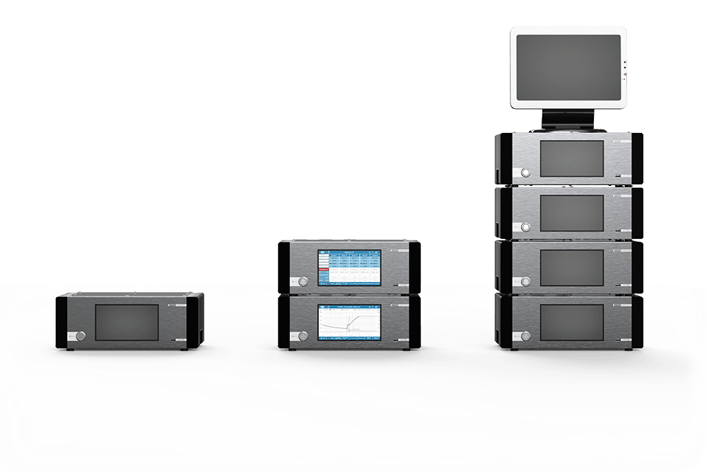
Three Thermonom hot runner controllers lined up next to each other

Hot runner controller with user-friendly & modern device concept

⇨ For precise temperature control and predictive control

The THERMONOM hot runner controller has a new, intuitive device concept that ensures precise temperature detection, the fastest switching processes, predictive control and several protective functions for the hot runner molds. A microprocessor controls the channels independently of each other, but can also combine them into synchronized groups.

Based on a network approach, several devices can be linked together via Ethernet and operated as a single, large functional unit. It can be operated from each individual device, from an industrial PC or from the process control station.

A new cost-effective approach

Current hot runner controllers for plastics processing must be able to cover applications with just one to more than 100 channels, which usually requires the development of different sizes of control technology.

The THERMONOM hot runner controller is available in a single size with optimum component utilization and minimum weight and space requirements. By networking several devices and a license model, any number of channels can be achieved.


An icon symbolizing the advantages of the Thermonom hot runner controller.
  • Favorable device price

  • Maintaining a stock of new appliances, short delivery times

  • Rental equipment service

  • Replacement devices available at any time for servicing

An icon that visually symbolizes the network functions of the Thermonom hot runner controller.
  • Remote support

  • Each channel has its own microprocessor, current and temperature measuring point

  • Up to 16 devices (192 channels) can be linked via Ethernet and operated as one functional unit, either from one device, from an industrial PC or from the process control station

An icon symbolizing the flexible design of the Thermonom hot runner controller.
  • Channels are activated via licenses

  • Subsequent activation of additional channels by entering a license code

  • Each hot runner controller device has 4 to max. 12 channels unlockable

CONTROL TECHNOLOGY. INTUITIVE. EFFECTIVE.

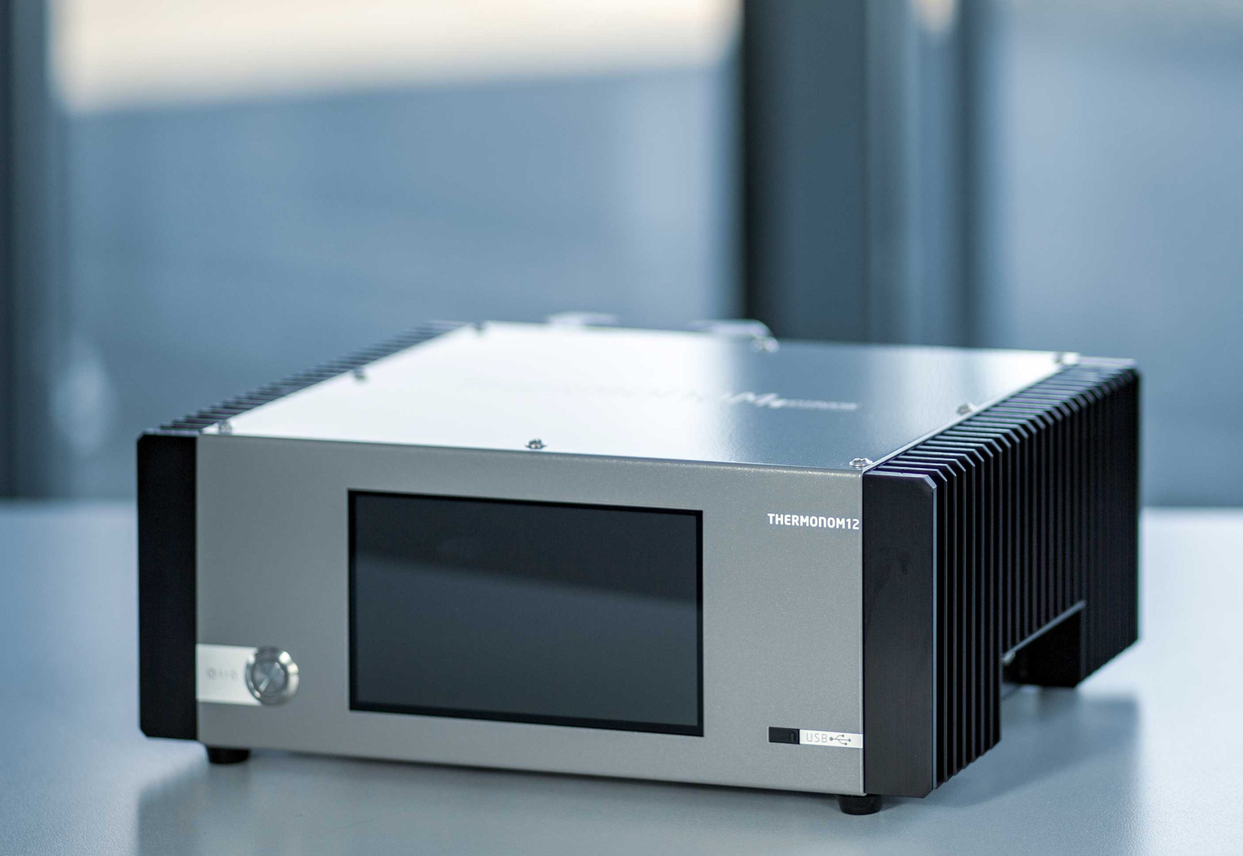
Thermonom hot runner controller, one level with 12 channels.
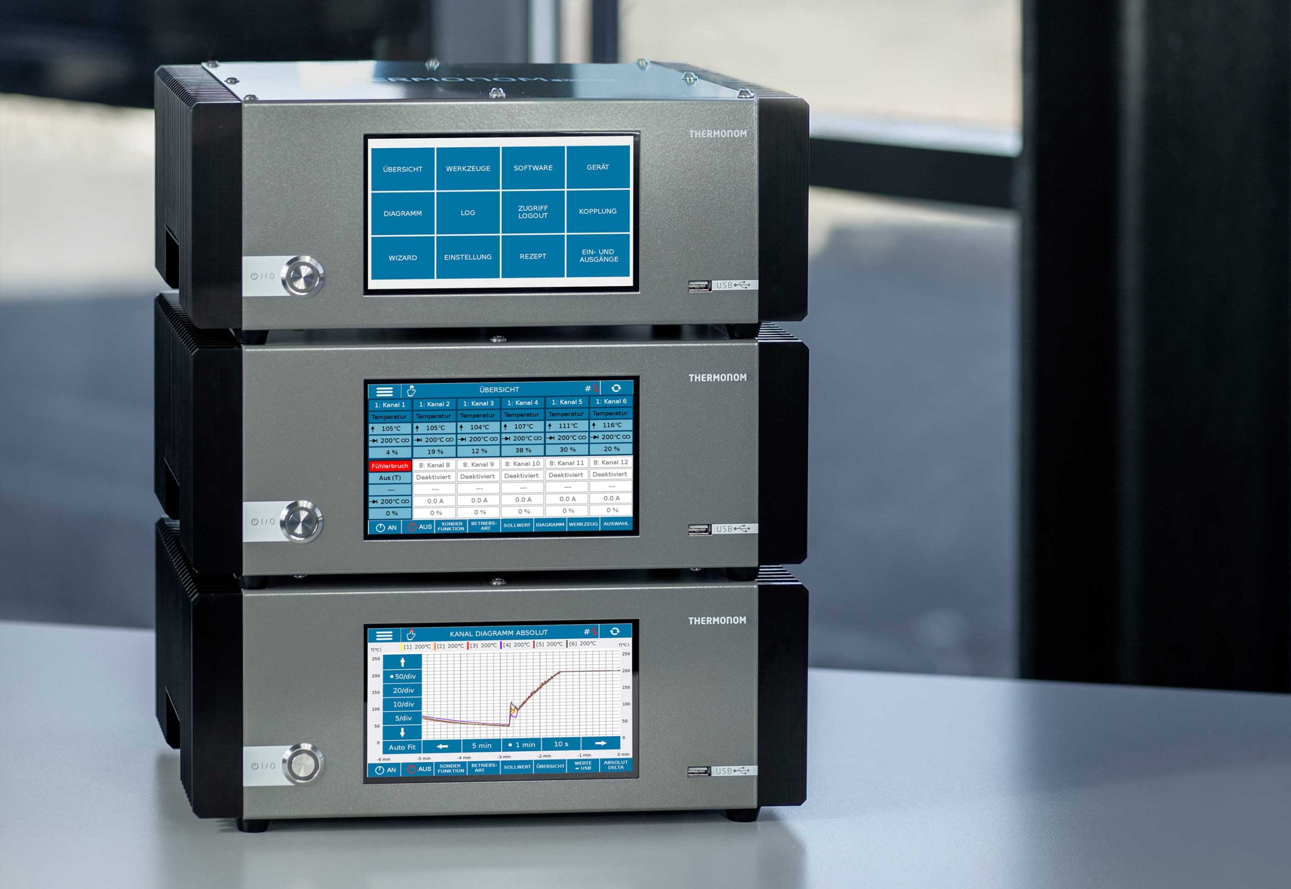
Switched-on Thermonom hot runner controller with 36 channels and 3 user interfaces.
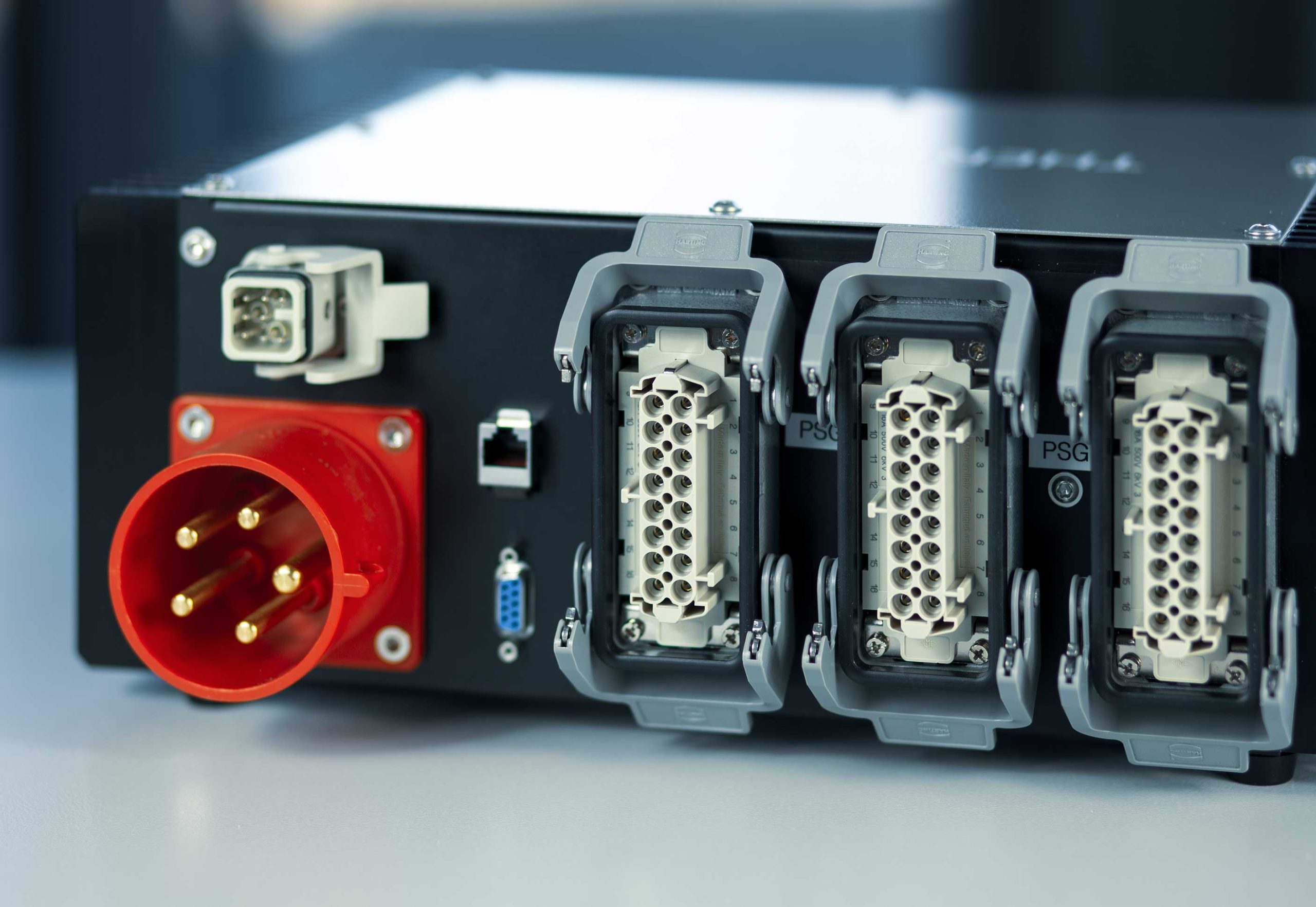
Thermonom hot runner controller, rear view with 12 channels, PSG

Characteristics of the THERMONOM hot runner controller

Icon for the reverse polarity protection of the hot runner controller.

REVERSE POLARITY PROTECTION

The THERMONOM hot runner controller detects incorrectly connected temperature sensors
Icon for the PID controller of the Thermonom hot runner controller.

PID CONTROLLER

  • Optimized PID controller with automatic adaptation
  • Synchronization of multiple, flexibly groupable control zones
Icon for the fanless version of the Thermonom hot runner controller.

FANLESS DESIGN

Fanless design of the hot runner controller, with convective cooling of the power electronics

Icon for the compact size of the Thermonom hot runner controller.

EXTREMELY COMPACT SIZE

  • Robust housing construction, anodized aluminium and stainless steel 1.4301 (V2A)
  • Barely larger than a DIN A4 page, weight 6.5 kg
Icon for the user interface of the Thermonom hot runner controller.

INTUITIVE USER INTERFACE

  • Clear user interface on 7″ touch display
  • Resolution 800 x 480 pixels
Icon for quick configuration of the hot runner controller.

FAST CONFIGURATION

  • Wizard – quick configuration when changing tools
  • Diagnostic function for toolmakers and setters

The user interface
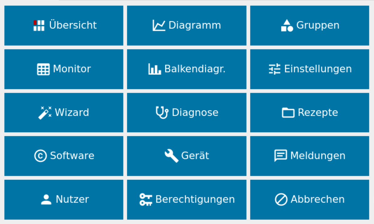
MAIN MENU

Direct access to all functions. Critical device settings of the hot runner controller can be protected against incorrect operation by user control.
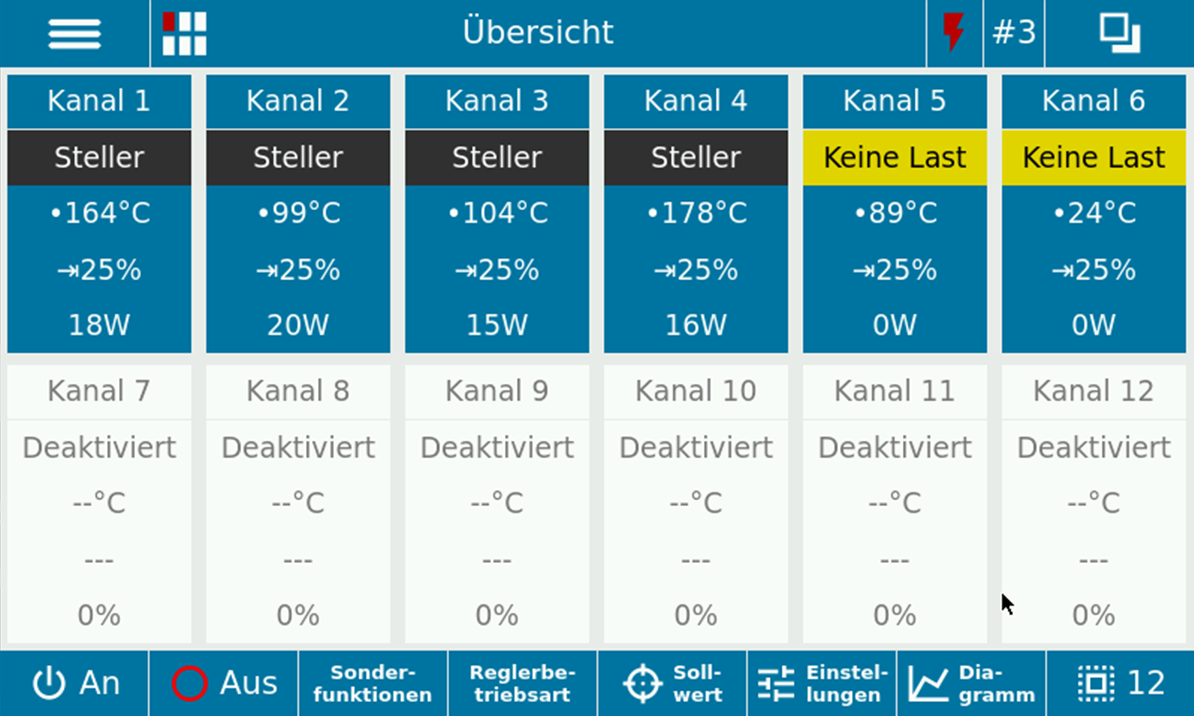
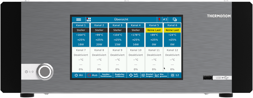
Kanalübersicht 6 Kanäle

CHANNEL OVERVIEW

The start screen shows an overview of all control zones and allows configuration with just a few clicks.
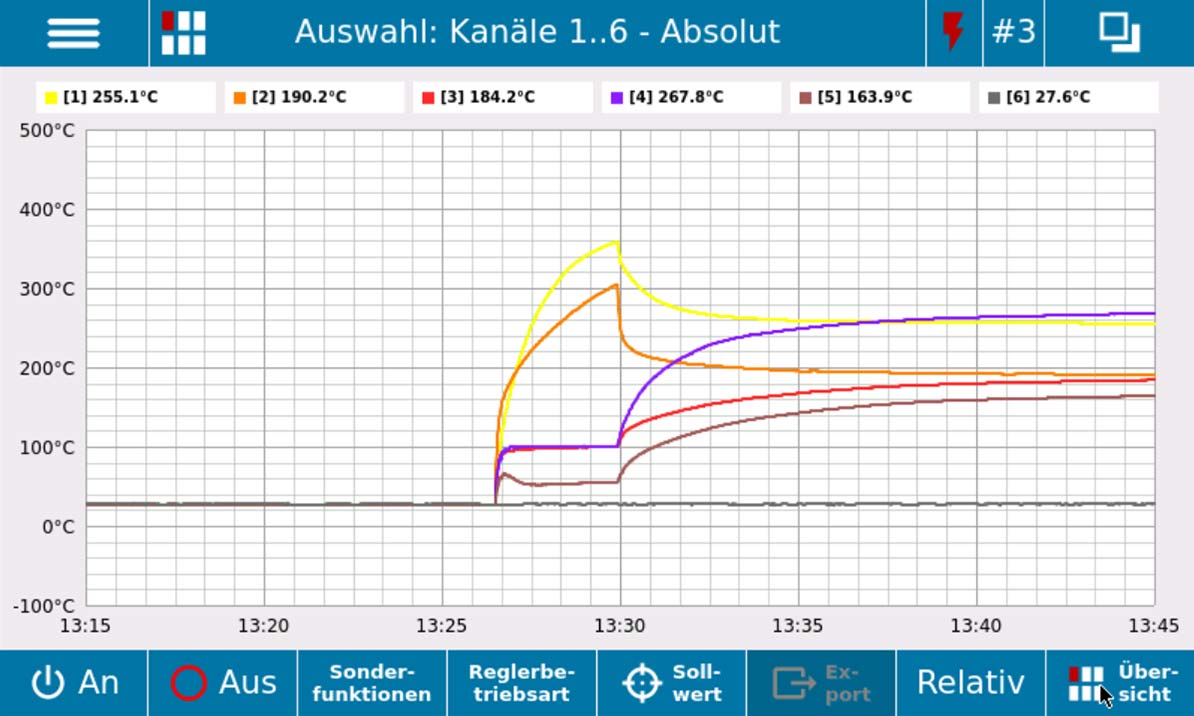
Diagramm Heizphase

DATA WRITER

Measured temperatures, output level and deviations from the setpoint can be processed and exported in an intuitively customizable diagram.

Specifications

Via Digital IO: Input-1: On/Off, Input-2: Standby, Input-3: Boost, Out-1: Ready, Out-2: Error
Serial: ARBURG TTY
Ethernet: Modbus TCP (PSG compatible)
Ethernet: OpcUA (optionally with encryption)
– Euromap 82.8 (coming soon)
– THERMONOM structure

USB (front panel): For data exchange via USB storage medium, operation via mouse, USB-T
Ethernet: For device coupling, software update & remote access, data logging, THERMONOM Cloud
RS485/232 and Can: interface for integration into the injection molding machine control system
HAN D socket, 8-pin: Two or three configurable potential-free inputs and outputs

Channel overview: Switching the channels on and off, special functions, operating modes
Groups: Functional scope of the channel overview applied to grouped channels
Diagram: Configurable data recorder, data export, relative and absolute display
Logbook: Error messages, warnings, diagnostics with export function
Wizard: Quick start after tool change, step-by-step configuration
Channel settings: Sensor types, current limits, behavior in the event of a fault, setting of special functions, control parameters, adaptation
Diagnostics: Fault determination, parameter determination, ageing comparison
Boost: Activation of frozen channels, configurable time and temperature
Setback: Temperature reduction during interruptions, temperature configurable
Synchronization: Synchronous heating of grouped channels
Soft start: Evaporation of residual moisture in the sensor insulation

Access: User administration, 3 access levels, user logon and logoff
Software: Display of firmware version, network status, update function
Device settings: Device temperature, behavior on restart, update functions
Device coupling: Connecting several hot runner controllers to form a functional unit, network search
Recipes: Saving and restoring channel settings, data export
Inputs and outputs: Programming or activation of the internal inputs and outputs

Cloud connection
RFID-CAN reader (tool & user identification)
Emergency stop circuit

  • Sensor break
  • Sensor polarity reversal
  • Protection of the sensor input against overvoltage
  • Detection of sensors connected to the load output
  • Short-circuit test of the load outputs before activation
  • Heating open (no load)
  • Heater alloyed through (short circuit)
  • Heating outside the current limits
  • Insulation fault

Configuration options

two times 24-pole,
arranged horizontally

Sketch of a 24-pin mold connector for the Thermonom hot runner controller.

two times 32-pole,
arranged vertically

once 32-pole,
once 40-pole

Sketch of a 40-pin mold connector for the Thermonom hot runner controller.

three times 16-pole,
arranged vertically

Sketch of a 16-pin mold connector for the Thermonom hot runner controller.

CEE plug 16 A
CEE plug 32 A
CEE plug 63 A

Sketch of a CEE32A connection from the Thermonom hot runner controller

Cable gland M32

M32 Anschluss
FEATUREVALUE
Dimensions(W x H x D) 360 x 137 x 307 mm
Weight6.5 kg
Heat sinkAluminium, black anodized
Lower housing shellAluminium, black anodized
Upper housing shellSteel RAL 9016
Installationhorizontal standing
Display7″ touchscreen, 800 x 480 pixels
Internal memory3 GB
Number of adjustable channels per devicemax. 12
Channels for device coupling192
Type Temperature sensorsJ and K
Control range20 – 800 °C
Display accuracy1 K
Number of inputs2 (potential-free)
Number of outputs3 (potential-free)
Supply voltage400 V +- 10% (3~, N, PE)
Mains frequency50 Hz
Maximum power output22 kW
Maximum current consumption32 A
Maximum current per channel16 A
Inrush current< 1 A
Protection classIP 30
Maximum heat sink temperature60 °C
Ambient temperature40 °C
Maximum relative humidity90 %

Always up to date!

Customer-oriented user interface with free updates

The user interface of our hot runner controller was developed taking into account many customer suggestions and will be continuously improved and adapted to current requirements in the future. Software updates are generally freely available and can be installed either via an existing network connection or via a USB storage medium.

For a future-proof injection molding process

Discover the possibilities for a future-proof
injection moulding process and revolutionize your production
with the THERMONOM hot runner controller.

For a future-proof injection molding process

Discover the possibilities for a future-proof
injection moulding process and revolutionize your production
with the THERMONOM hot runner controller.

About us

Production & Support
Intronik logo

Intronik GmbH
Am Promigberg 8 | D – 01108 Dresden

Phone +49 (0) 351/88 21-55
Fax +49 (0) 351/88 21-28

Mail info@intronik.de
Web www.intronik.de

Distribution
Nadler-Kunststofftechnik logo

Kunststofftechnik Nadler GmbH & Co KG
Heinrich-Cotta-Straße 5 | D – 01324 Dresden

Phone +49 (0) 351/26 55 128-0
Fax +49 (0) 351/26 55 128-1

Mail kontakt@kunststofftechnik-nadler.de
Web www.kunststofftechnik-nadler.de